
Introduction
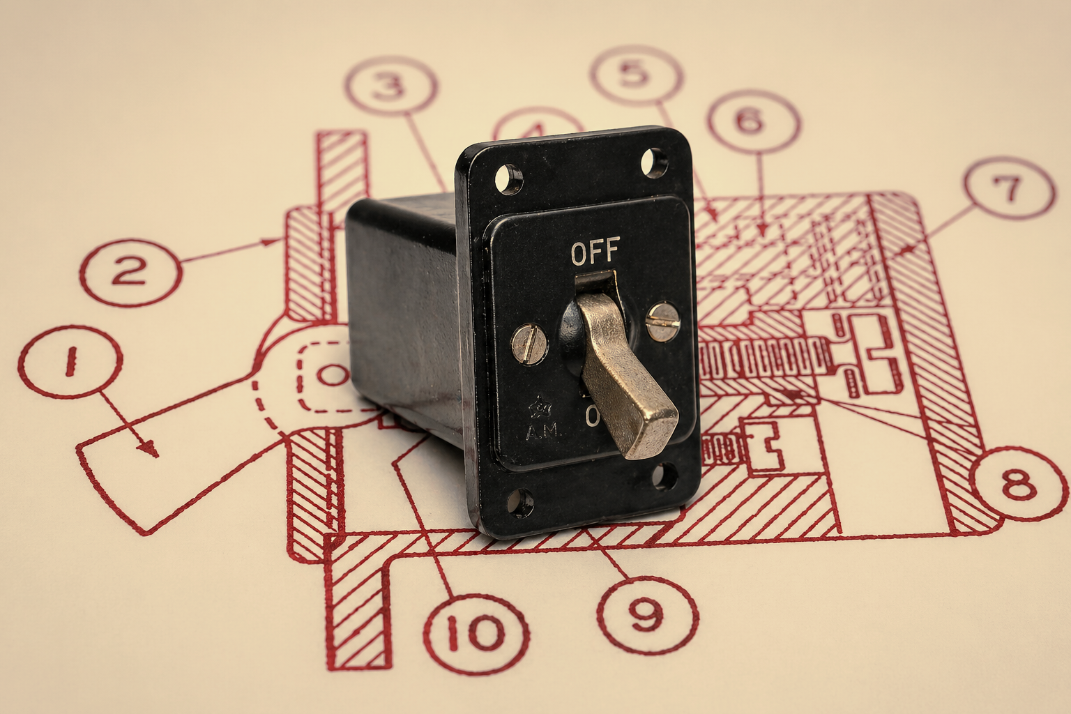
This small on/off switch was fitted in almost every British military aircraft of the Second World War: the Switch Type B with Air Ministry Stores Reference 5C/543. It controlled, amongst other things, the navigation lights, the Reflector Gun Sight, cameras, and the pitot heater in the Supermarine Spitfire. What first caught my attention was how much engineering had gone into what is, at the end of the day, just an on/off switch. Nor has anyone, to my knowledge, thought to document why nominally identical examples bearing the same designation can differ so markedly from one another. Air Publication 1095A describes the construction in dry, technical terms, but leaves out precisely the details that stood out to me on closer inspection. As far as I have been able to determine, no one has ever examined this switch in this level of detail before.
Designation and function
The switch is officially catalogued as “Switch Box, Type B, One Unit” in the Air Ministry Vocabulary of Stores (AP1086).[1] It is documented in Section VII, Chapter 1 of Air Publication 1095A under the title “General Purpose Switchboxes, Type B”.[2] Its stated purpose is defined as follows:
“These switchboxes consist of single-pole switches mounted one or more in a box arranged for flush mounting on a panel, and are for use in aircraft to control circuits in which the current does not exceed 20 amperes.”
Single-pole, maximum switching current of 20 A, designed for the typical 12 V and 24 V DC electrical systems of British military aircraft.
Use in the Spitfire cockpit
The Spitfire is probably the easiest place to appreciate just how widespread the 5C/543 really was. The exact number of switches fitted and their individual functions vary considerably between Marks and modification states, and to my knowledge no complete list has ever existed. Until now.
I have worked through the Pilot’s Notes for every Spitfire variant and extracted every Switch Type B mentioned, together with its panel number and exact functional description. The original spelling and capitalisation have been preserved throughout, which usefully reveals that neither was entirely consistent.
Spitfire I & II[3]
- Pressure head heating switch (No. 5)
- Camera gun master switch (No. 6)
- Navigation lamps switch (No. 24)
- Reflector sight main switch (No. 54)
- Generator switch (No. 60)
Spitfire V[4]
- Pressure head heater switch (No. 55)
- Camera-gun switch (No. 53)
- Navigation lights switch (No. 46)
- Reflector Sight Main Switch (No. 9a)
- R. 3108 master switch (No. 93)
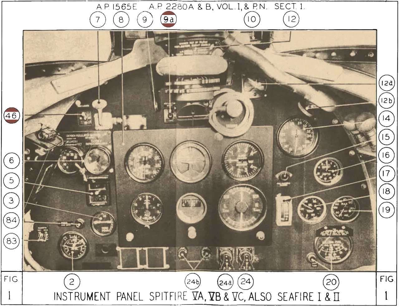
Spitfire Mk. V instrument panel from Pilot’s Notes showing Switch Type B positions
Spitfire IX[5]
- Pressure-head heater switch (No. 28)
- Navigation lamps switch (No. 4)
- Reflector sight switch (No. 8)
- IFF master switch (No. 55)
Spitfire F XII[6]
- Pressure-head heater switch (No. 28)
- Navigation lamps switch (No. 4)
- Reflector sight switch (No. 8)
- IFF master switch (No. 55)
Spitfire 16[7]
- Pressure head heater switch (No. 20)
- Camera master switch (No. 19)
- Fuel booster pump switch (No. 18)
- Gyro gun sight master switch (No. 42)
- IFF or demolition switch 1 (not described, but visible)
- IFF or demolition switch 2 (not described, but visible)
Spitfire VI[8]
- Pressure head heating switch (No. 51)
- Camera gun switch (No. 50)
- R. 3002 master switch (No. 69)
Spitfire VII & VIII[9]
- Navigation lights switch (No. 19) *
- Pressure-head heater switch (No. 18) *
- Camera gun heater switch (No. 17) *
- Beam approach master switch (No. 59)
Spitfire XIV & XIX[10]
- Navigation light switch (No. 52) *
- Pressure-head heater switch (No. 51) *
- Camera gun heater switch (No. 50) *
- Fuel booster pump switch (No. 49)
- Beam approach master switch (No. 57)
- IFF distress switch (No. 70)
- IFF main switch (No. 69)
Spitfire 18[11]
- Navigation lights switch (No. 51) *
- Pressure-head heater switch (No. 50) *
- Cine camera heater switch (No. 49) *
- Recognition light selector switch (No. 54)
- Gyro gun sight master switch (No. 57)
- IFF or demolition switch 1 (not described, but visible)
- IFF or demolition switch 2 (not described, but visible)
* Fitted as the 3-Unit variant 5C/544
Spitfire 21[12]
- Navigation lights switch (No. 22) **
- Pressure-head heater switch (No. 22) **
- Cine camera heater switch (No. 22) **
- Fuel booster pump switch (No. 22) **
- Gyro gun sight master switch (No. 43)
- Demolition Switch 1 (No. 47)
- Demolition Switch 2 (No. 47)
** Fitted as the 5-Unit variant 5C/545
Spitfire 22 & 24[13]
- Booster pump selector switch (No. 34)
- Recognition light master switch (No. 41)
- Ciné camera master switch (No. 42)
- IFF or demolition switch 1 (not described, but visible)
- IFF or demolition switch 2 (not described, but visible)
Use in other RAF aircraft
Beyond the Spitfire, the 5C/543 appeared in virtually every operational British type: Hurricane, Lancaster, Halifax, Mosquito, Beaufighter, Wellington, and many besides. It was equally standard in the Fleet Air Arm’s Seafire, whose cockpit layout followed the Spitfire closely.[14]
Technology and construction
The casing material: Bakelite
Bakelite is a phenol-formaldehyde resin and is regarded as the world’s first fully synthetic plastic. Developed in 1907 by the Belgian-American chemist Leo Baekeland, the material found widespread use in electrical engineering from the 1920s onwards and remained virtually unrivalled in that role well into the 1950s.[15]
Looking at the requirements, it is easy to see why Bakelite was chosen: Bakelite is an excellent electrical insulator, heat-resistant well above 100 °C, dimensionally stable under mechanical load, and relatively easy to mould into complex shapes. For a component required to carry switching currents of up to 20 A inside a vibrating, temperature-fluctuating aircraft cockpit, it was the natural choice.
Air Ministry documentation, as was customary at the time, avoids the brand name and refers generically to “black moulded insulating material”. The characteristic dark-brown to black colour of original 5C/543 bodies is typical of Bakelite based on phenolic resin with wood flour filler.
Construction and components
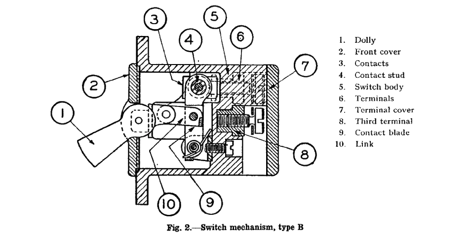
Body: The body, front cover, and terminal cover are all made of “black moulded insulating material”, that is, Bakelite.
Contacts: The two fixed contacts are of phosphor bronze and are secured within the body by the terminals.[16]
Switch mechanism: The dolly (1) is centrally pivoted on a bridge across the front of the switch body (5), into which the front cover (2) is secured by two screws. A double-pivoted link (10) connects the dolly to the contact blade (9). The contact blade comprises two metal arms pivoted at their lower ends and joined at their upper ends by a fixed copper contact stud, which is insulated from the blade by Bakelite washers on both sides. Two torsion springs at the pivot point bear against the arms, pressing them forward under constant load. When the dolly is moved from the off position down to the on position, lever action drives the contact blade rearward through the link, forcing the contact stud between the two fixed contacts and completing the circuit. It is this rearward press fitting between the contacts and the stud that accounts for the resistance felt through the mid-position. Once the link passes through dead centre (its horizontal position of maximum resistance), the peak of required force is reached and falls away sharply, driving the dolly into the on position with the characteristic snap.[17]
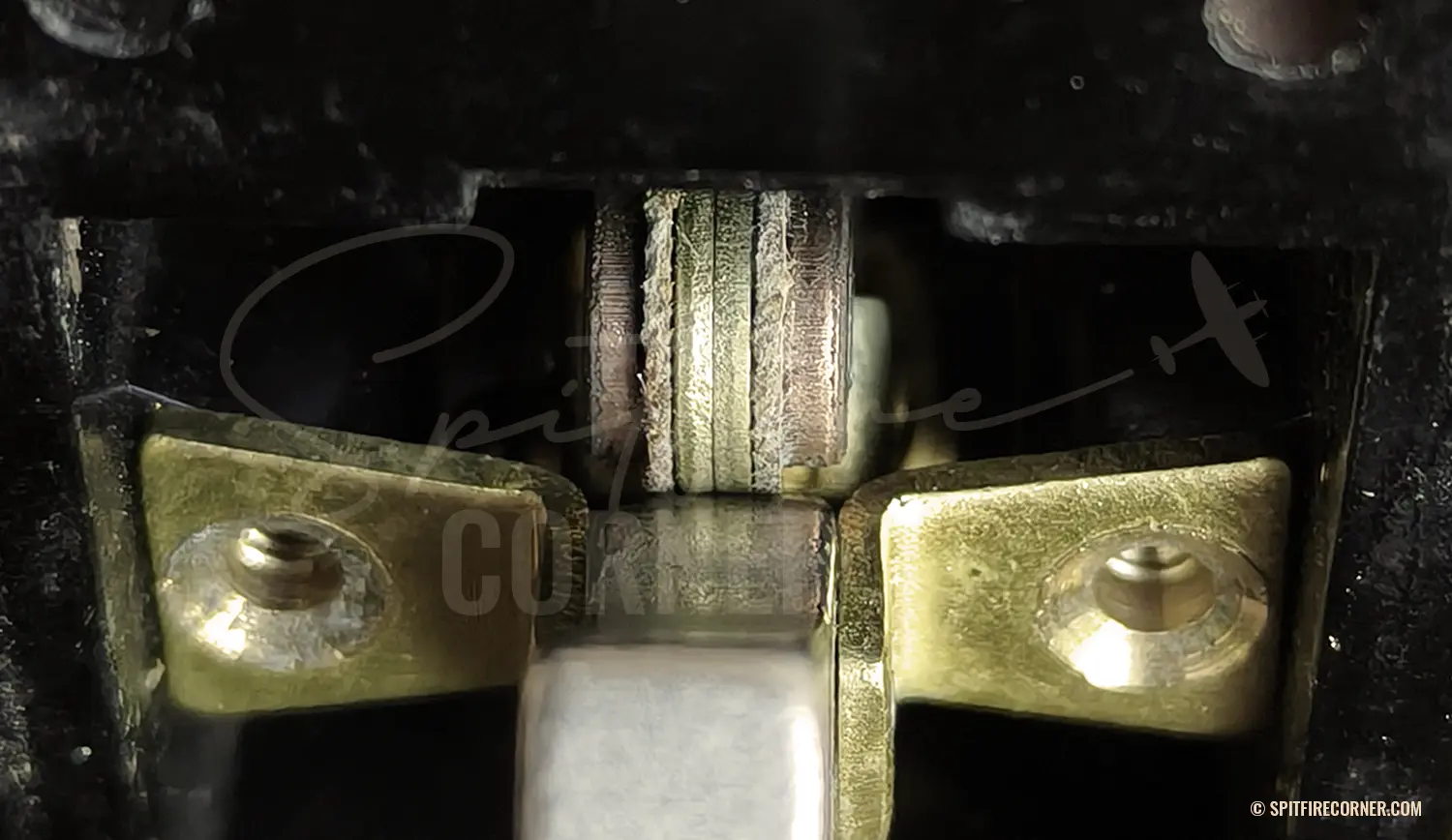
Insulation washers between both arms and the contact stud
Terminals: At the back of the switch, the terminals pass through the body and are fastened with screws and washers. A third terminal provides the lead-in for the unswitched pole; in the multi-unit versions (5C/544 and 5C/545), these third terminals are internally linked via a bridge within the Bakelite body.[18]
Related variants and modifications
The 5C/543 is the single-unit version of a three-part family. Where several switches logically belonged together, the multi-unit variants were used:
- 5C/544 — 3-Unit Switch Type B: Three identical, independent switches sharing a common Bakelite body, frequently found on the side consoles of larger aircraft for grouped lighting and heating circuits.
- 5C/545 — 5-Unit Switch Type B: Five identical, independent switches in a common Bakelite body, typical of Mosquito and Lancaster cockpits. The Spitfire 21 is, according to its Pilot’s Notes, the only Spitfire Mark to have used this 5-unit version.
No permanently coupled 2-unit or 4-unit version with its own Stores Reference exists; where paired operation was required, two 5C/543 switches were mechanically linked using perforated dollies and a linking bar.
For safety-critical applications, a spring-loaded protective guard (Stores Reference 5C/2823) could be fitted over the dolly.[19] It had to be flipped up before the switch could be operated, preventing accidental actuation.
Circuits
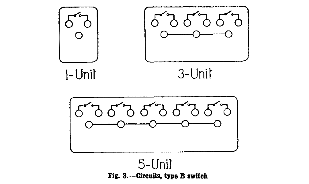
Dimensions and mounting
AP1095A gives the following dimensions and weights for the three variants:[20]

Mounting and panel cut-out:
The component is fixed to the panel through four holes in the switch body using four 6-BA (British Association) screws, or alternatively four No. 4 wood screws.
According to Blueprint No. 32934 SHT23 for the Spitfire instrument panel, the cut-out for the front cover measures 1.16 in (29.46 mm) wide and 1.3 in (33.02 mm) high, with corner radii of 0.15 in (3.81 mm). The four mounting holes are arranged in a rectangle, with a horizontal centre-to-centre spacing of 0.86 in (21.84 mm) and a vertical spacing of 1.58 in (40.13 mm). The diameter is not stated; instead, the drawing reads:
4-HOLES TO SUIT SWITCH-BOX TYPE “B” REF. No 5c/543.
A 6-BA screw has a diameter of 0.110 in (2.8 mm), which means the clearance holes in the panel should ideally be 0.12 in (3.044 mm).
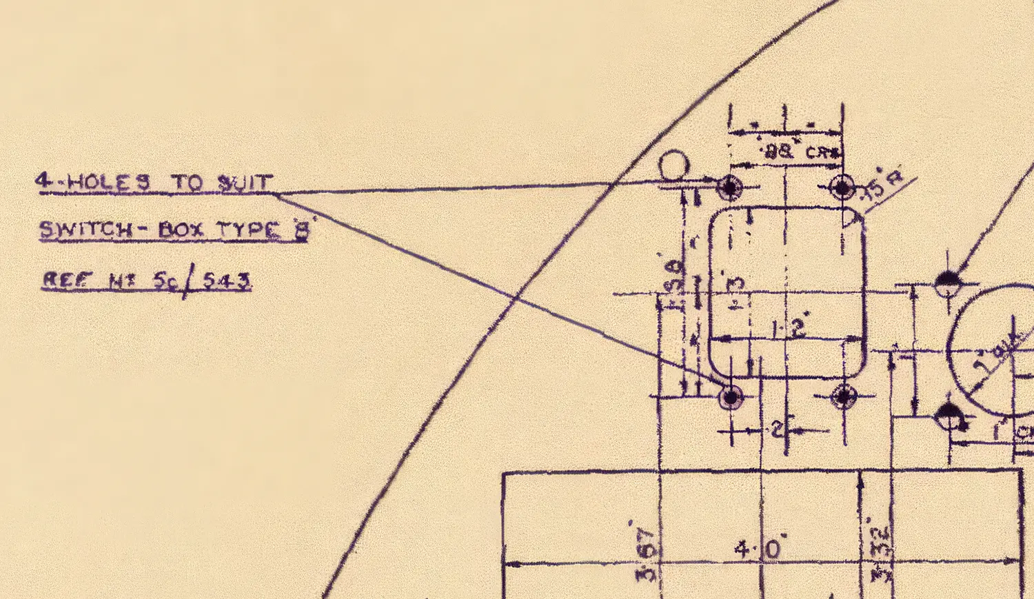
Spitfire panel Blueprint No. 32934 SHT23 showing mounting dimensions for Switch Type B 5C/543
Variations: four examples compared
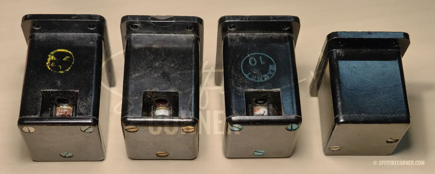
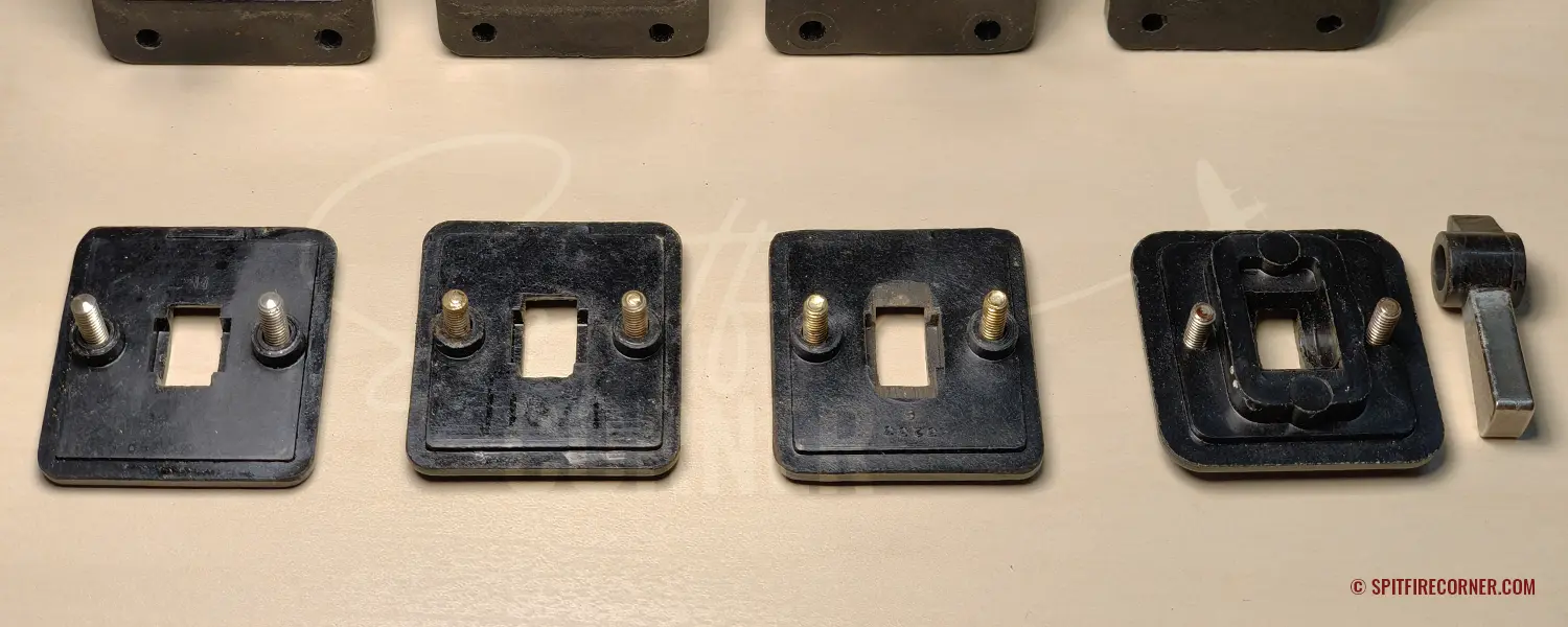
I own over 20 original Switch Type B switches (1-unit) and have noticed that, while they all carry the same Stores Reference 5C/543, they can differ noticeably in construction, dimensions, front-cover layout, and dolly manufacturing method.
I couldn’t find any record identifing the manufacturer or the precise period of production. Based on the low sequential number within the 5C section and the fact that it was already fitted to the Spitfire Mk I (which entered service in August 1938), it is reasonable to infer that the switch was specified in the mid-1930s, probably around 1936. Production also continued well beyond the war’s end, into the early 1950s, as evidenced by factory-sealed New Old Stock examples in my collection dated 1953.
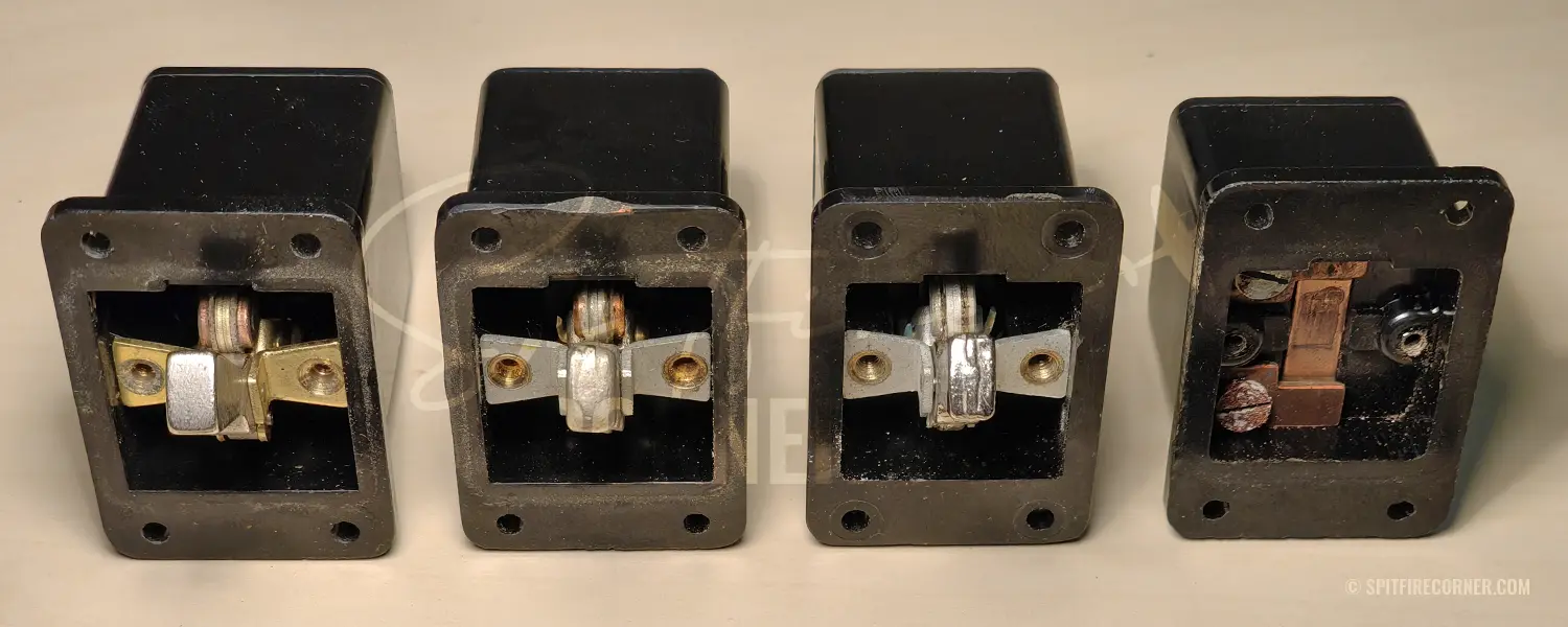
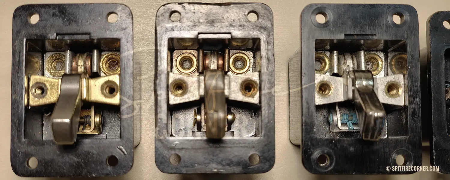
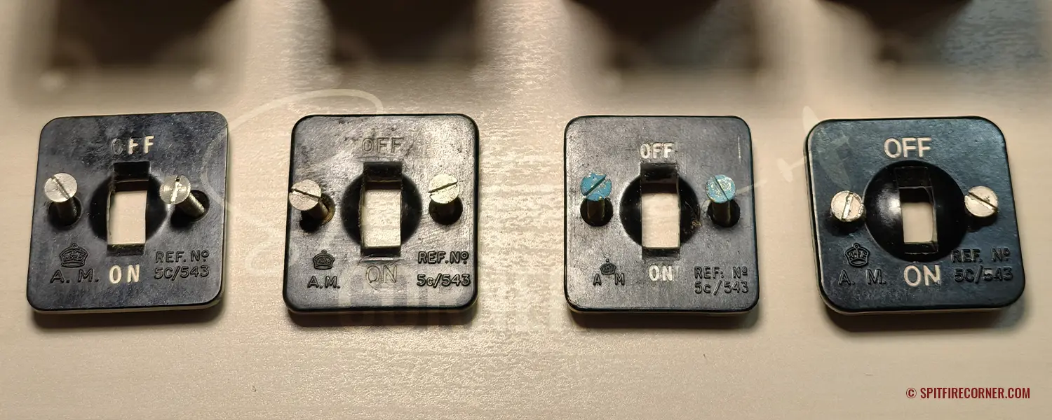
To illustrate these differences, I have selected four switches that diverge clearly from one another and were in all likelihood produced during different periods (and/or different manufacturers). Some of these differences offer useful pointers for placing each switch within a plausible production window. The periods suggested below rest on the assumption that manufacturing methods and material choices evolved in response to wartime conditions.
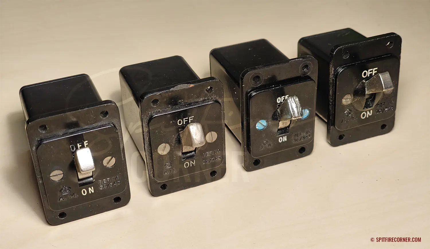
Four Air Ministry Switch Type B 5C/543 showing clear differences in construction and front cover design
The four switches in the photographs are arranged from left to right in this assumed chronological order and are numbered 1 (far left, oldest) to 4 (far right, most recent). Switch No. 3 is a New Old Stock example with a verified packing date of May 1953.
A different switching mechanism and size
The first thing that jumps out is that switch No. 4 is fundamentally different from the other three.
Switch No. 4, at 39 mm, is approximately 9 mm shorter than Nos. 1 to 3. The dome on the front cover around the dolly is also far more pronounced, with its diameter exceeding that of the cut-out itself. When I opened the switch for the first time, I expected to find the familiar AP1095A mechanism inside. But the internal layout of switch No. 4 is entirely different and considerably simpler. The dolly is retained solely by the dome in the front cover. In the off position, the dolly’s tapered rear profile presses a spring-loaded contact plate firmly rearward, holding the circuit open and the dolly clamped by spring tension. Flipping the dolly to on relieves that pressure, allowing the spring to push the plate forward onto the two terminals and close the circuit.This design bears no resemblance to the layout described in AP1095A, as represented by switches 1 to 3, which leads me to suspect it is a post-war redesign that saw no wartime service.
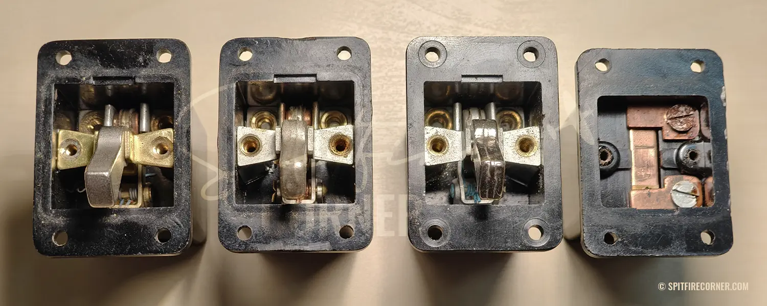
Variations in the front cover
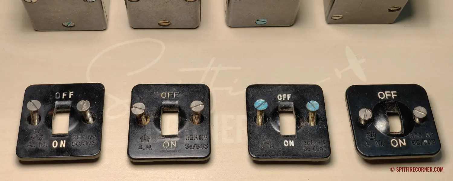
Viewed side by side, a further difference is immediately apparent: no two front covers are alike.
All covers consistently display the following information:
- The positions “ON” / “OFF” are stamped in white above and below the dolly
- The Air Ministry crown (A♛M) is shown in the lower left
- The Stores Reference 5C/543 is shown in the lower right
As the photographs make clear, however, the execution varies considerably from switch to switch:
- Differing typeface and font size
- Differing size and style of the Air Ministry crown, A♛M or A.♛M. with and without abbreviation points
- Differing font size of the Stores Reference
- Differing dome size, as noted above
Dolly material and manufacturing method
A further notable difference lies in the dollies themselves. Both the manufacturing method and the material vary between examples, and this is immediately apparent to the eye.
AP1095A contains an interesting clue:
“The dolly is of nickel-plated brass in switches of later manufacture, and is pivoted on a bridge at the front of the switch.”[21]
The phrase “in switches of later manufacture” clearly implies that an earlier version with a different dolly material existed. The AP does not specify what that earlier material was. AP1095A notes that this chapter was last revised in November 1943. Unless the publication lagged significantly behind production, this would place the change no later than 1943.
In footage from the 1940 instructional film Daily Inspection of a Spitfire[22], two 5C/543 switches from the early war years are clearly visible. Based on this footage and the generally higher manufacturing standards of the pre-war period, I am fairly confident that the earlier dollies (No. 1, far left in my examples) were stamped, as evidenced by their crisp edges and precise form. Later dollies appear to have been cast (switches 2 and 3), as indicated by the visible parting line running down the centre and the coarser surface finish. The polished dolly of switch No. 3, demonstrably one of the last examples in the original configuration given its packing date, is in all likelihood the nickel-plated brass referred to above, lending further weight to a late production date.
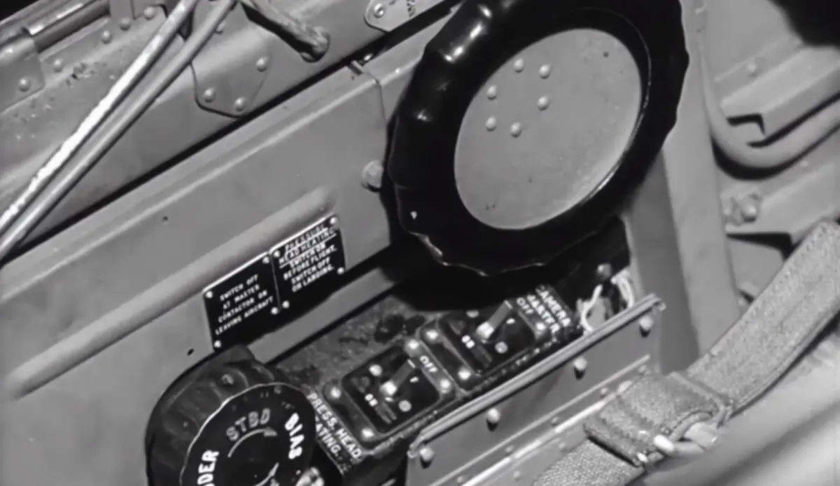
Switchbox Type B seen in original Air Ministry footage from 1940
Dating through photographic evidence
The famous photograph of the Mk II D Gyro Reflector Gun Sight from 17 August 1944[23] shows the corresponding master switch in remarkably sharp detail. This is once again switch No. 1 from my comparison examples (sharp-edged dolly, small dome, large A♛M crown). This confirms that the No. 1 design was definitely in use during the Second World War and is fully authentic.
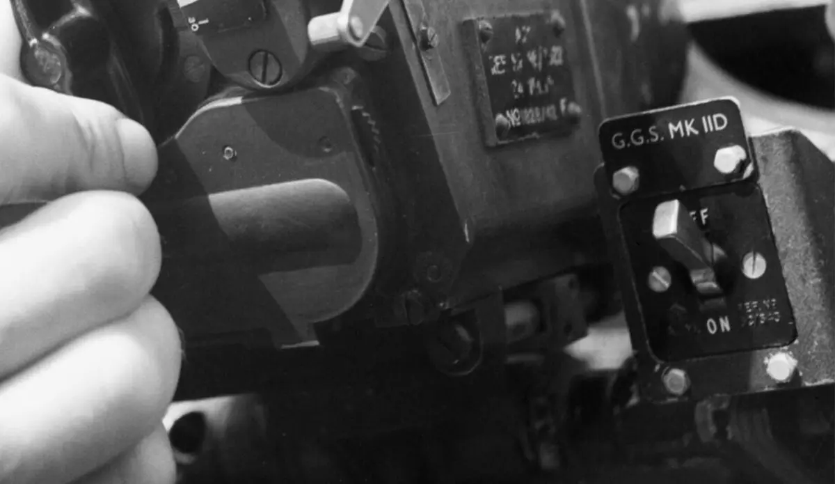
Authentic photograph from 17. August 1944 showing a Type B Switch
Another highly reliable source is the book Spitfire LF. Mk. IX in Detail, which documents the Supermarine Spitfire Mk IX TE-565 in extraordinary detail through hundreds of photographs. Most pertinent here is the following passage:
“On this double-page there are three overall views of the TE-565 cockpit, likely the most complete original interiour of a Spitfire Mk. IX, as it was not flown after the crash on April 22 1949, remaining without any changes in contrast to the aircraft that served with various air forces after the war and have been flown until now.[24]“
The photographs are not published here, as the book remains in copyright. Working from them directly, I located every Switch Type B visible, compared each with my four selected examples, and assigned it to its corresponding type number.
- Pressure head heater switch: No. 4
- Camera master switch: No. 4
- Fuel booster pump switch: No. 4
- Navigation lights switch: No. 3
- Gyro gun sight master switch: No. 2
- Beam approach master switch: No. 3
- IFF or demolition switch 1: No. 4
- IFF or demolition switch 2: No. 4
Given the longevity of this component, we must assume that not every Switch Type B was replaced after the war. Whatever its exact origin, No. 4 must have existed before April 1949. Whether it was also fitted during wartime service remains an open question.
This analysis also suggests that Nos. 2 and 3 were most likely fitted during wartime, but subsequently produced in considerably greater quantities and by more efficient means than No. 1.
Collector market
Prices and buying recommendation
Factory-sealed 5C/543 switches are well known and actively sought by collectors. Given the high production numbers and wide fitment, however, they are not especially rare. On eBay UK, examples come up regularly between £20 and £60, though condition varies considerably. Genuine originals can be identified by the Air Ministry crown, the embossed Stores Reference, the characteristic Bakelite body, and the silver dolly. New Old Stock examples are particularly common and are usually dated to the early 1950s, typically 1953. This is not an indication of reproductions or anomalies: the Spitfire and Seafire remained in RAF and FAA service well into the 1950s, and post-war types such as the Lancaster MR.3, Shackleton, Lincoln, and Sea Fury also used the same standard switch. Procurement therefore continued, with the specification unchanged from wartime production. A 5C/543 made in 1953 is mechanically and materially identical to one from the war years.
Based on the variations identified, my preference would be for 5C/543 examples with a deep body, a crisp-edged dolly, and a prominent A♛M crown, as these are most likely to date from the early war years and therefore represent the most authentic choice for restorations or simulator builds.
Original packaging
I am personally familiar with two types of original packaging for NOS examples:
1. Single unit wrapped in wax paper and sealed in plastic
NOS examples of the 5C/543 are frequently found sealed in clear plastic with the following text printed inside:
F.PKG. 66 (Gummed small)
NOT TO BE OPENED UNTIL REQUIRED FOR USE
5C 543
SWITCH, TUMBLER
Type B
Qty 1
A separate label records the packing date along with the “Method” and “Table” entries. All switches in my collection bearing this packaging were packed in April or May 1953. Unfortunately, this still tells us nothing precise about when the switches themselves were made.
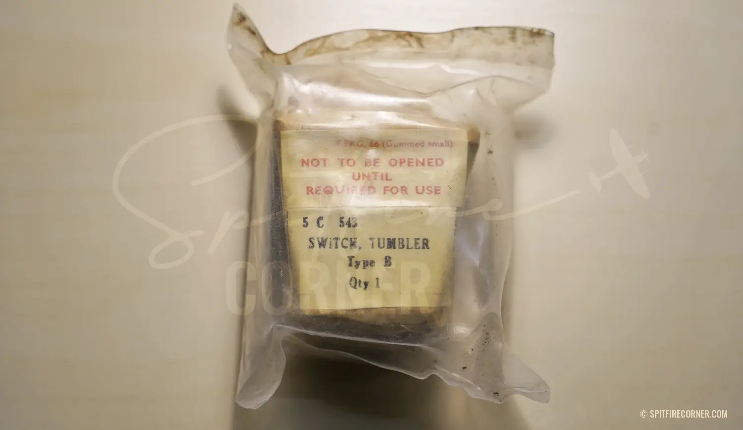
Sealed NOS Switch 5C/543
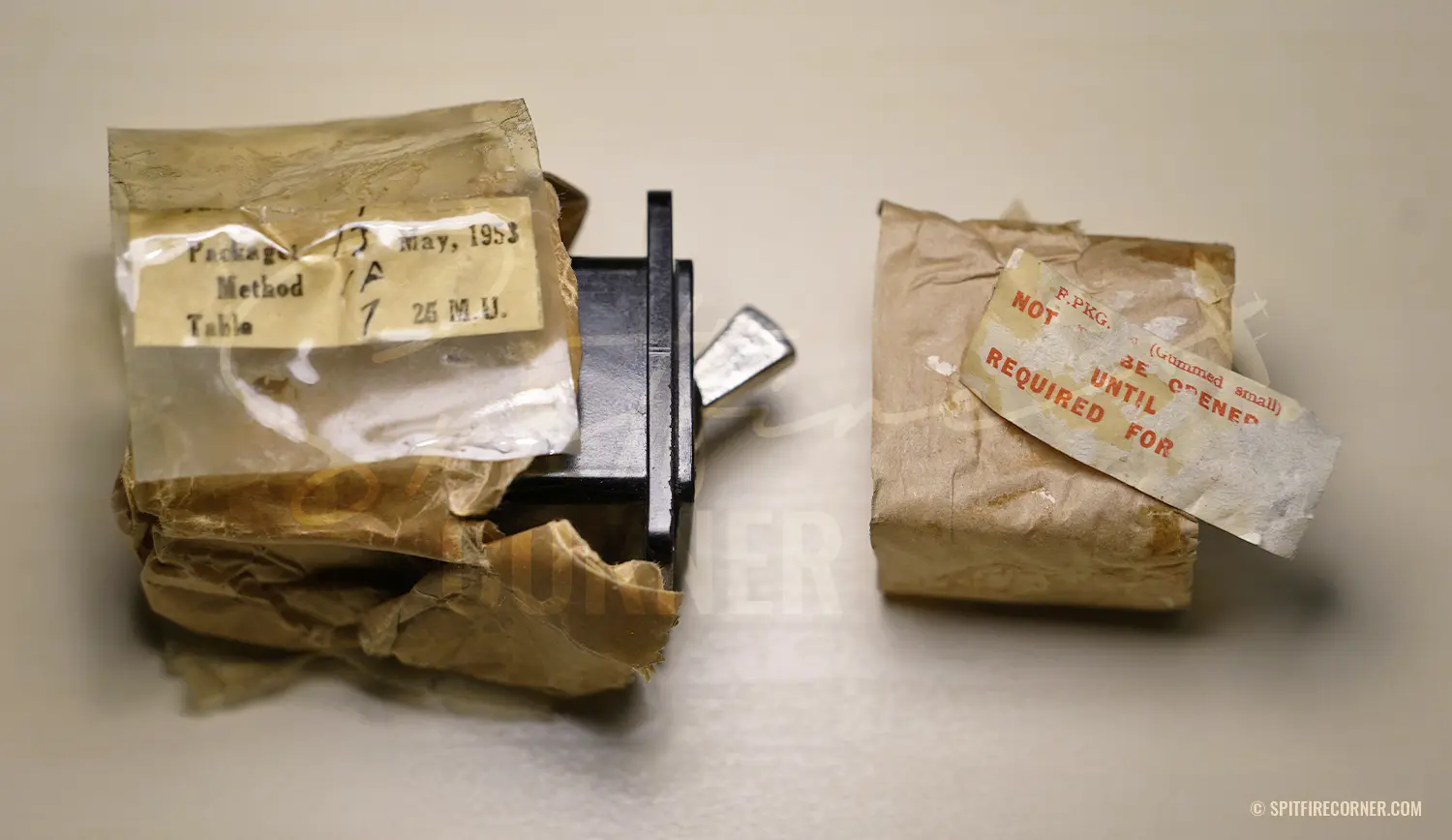
Wax paper with label after opening it up
2. Single unit in a cardboard box
Somewhat rarer and harder to find are individual switches supplied in a cardboard box with the following inscription:
THIS CARTON CONTAINS ONE SWITCH BOX ONE UNIT TYPE “B” REF No. 5c/543
or
A. ♛ M. This Box Contains One only Switch Box One Unit Type “B” Ref. No. 5C/543
Conclusion
At first glance, the Switch Type B 5C/543 would seem hardly to merit such extended treatment: a component largely overlooked, despite having been fitted hundreds of thousands of times in cockpits to operate systems on which pilots’ lives depended. The more examples I examined, the more respect I gained for the people who designed it.
What I find genuinely remarkable is that, for relatively modest outlay, one can acquire an authentic component from a real Supermarine Spitfire or any number of other RAF aircraft of the period, and with it a tangible piece of aviation history. Original cockpit parts are growing scarcer and more expensive, but this particular component remains a real bargain once you know what to look for. For flight simulator enthusiasts, the authentic feel, the genuine click, and the satisfying resistance of the dolly add considerably to the immersion of a virtual cockpit, and for my part I would choose an original over even the finest replica without hesitation. As a desk display it holds its own equally well, and those with a practical bent can of course put it to functional use.
Accuracy matters greatly to me in everything published here. If anyone has further information or evidence that can refute, confirm, or expand upon my conclusions, please do get in touch by email at hello@spitfirecorner.com.
Thank you for reading.
References
- Air Ministry: AP1086 — Vocabulary of Stores. Entry “Switch Box, Type B, 1 Unit”, Section 5C.
- Air Ministry: AP1095A, Vol. I — Electrical Equipment Manual, General (Airborne), Section VII, Chapter 1: “General Purpose Switchboxes, Type B”. Issue October 1943. Available online via R.A.F. Henlow Signals Museum / Colin Hinson, blunham.com/Radar.
- Air Ministry: Pilot’s Notes for Spitfire I — Aeroplane with Merlin II Engine. PDF via WW2Aircraft.net Forum, link.
- Air Ministry: Pilot’s Notes for Spitfire VA, VB and VC. PDF via stephentaylorhistorian.com, link.
- Air Ministry: Pilot’s Notes for Spitfire F IX. PDF via WW2Aircraft.net Forum, link.
- Air Ministry: Pilot’s Notes for Spitfire F XII. PDF via WW2Aircraft.net Forum, link.
- Air Ministry: Pilot’s Notes for Spitfire 16. PDF via WW2Aircraft.net Forum, link.
- Air Ministry: Pilot’s Notes for Spitfire VI. PDF via WW2Aircraft.net Forum, link.
- Air Ministry: Pilot’s Notes for Spitfire VII & VIII. PDF via WW2Aircraft.net Forum, link.
- Air Ministry: Pilot’s Notes for Spitfire XIV & XIX. PDFs via WW2Aircraft.net Forum, part 1 and part 2.
- Air Ministry: Pilot’s Notes for Spitfire 18. PDF via WW2Aircraft.net Forum, link.
- Air Ministry: Pilot’s Notes for Spitfire 21. PDF via WW2Aircraft.net Forum, link.
- Air Ministry: Pilot’s Notes for Spitfire 22 & 24. PDF via WW2Aircraft.net Forum, link.
- Air Ministry: Pilot’s Notes for Seafire I, II & III. PDF via WW2Aircraft.net Forum, link.
- American Chemical Society: “Bakelite — The World’s First Synthetic Plastic”. National Historic Chemical Landmark, 1993.
- AP1095A, Section VII, Chapter 1, §4.
- AP1095A, Section VII, Chapter 1, §5.
- AP1095A, Section VII, Chapter 1, §6.
- RAF-Surplus.co.uk, Electrical Components Section: entry “Switch Guard, Stores Ref. 5C/2823”, documented as a safety cover for the 5C/543.
- AP1095A, Section VII, Chapter 1, §7 (table “Particulars of the types”).
- AP1095A, Section VII, Chapter 1, §5 (verbatim).
- Film “Daily Inspection of a Spitfire” Part 2 @5:56 min, Imperial War Museum, link.
- IWM (CL 854), link.
- Page 90, Book “Spitfire LF. Mk. IX in Detail”, Wings and Wheels Publications, ISBN: 8086416259
Table of Contents
Liked this content?
There are many ways to support my work
This small On/Off switch was fitted in almost every British military aircraft of the Second World War: the Switch Type B with Air Ministry Stores Reference 5C/543.